

Due to the complexity of LED screens as precise electronic products, customers are inevitably faced with various issues during long-term usage. Sending them back to China for repairs from overseas incurs significant costs and time.
Learning to troubleshoot and address some simple faults can be a great choice, saving both the cost and time of returning the product for repair.
LED screens consist of various components, and any malfunction in these components can lead to issues during usage. Therefore, we have divided the troubleshooting and solutions into six sections to address LED display screen problems systematically.
It’s recommended for engineers with repair needs and customers seeking to address LED screen issues to keep this guide for long-term reference.
We prioritize addressing issues according to severity in this comprehensive guide to LED screen troubleshooting and repair.
Troubleshooting and Repair of LED Screen not Working
I. Circuit Board Short Circuit and Solutions (Highest Priority)
Circuit board shorts need to be detected using a multimeter for resistance, voltage, and short-circuit information. Then, solutions should be applied based on the identified problems. Most circuit board issues cannot be resolved by customers themselves and require sending the LED module back to the manufacturer for repair.
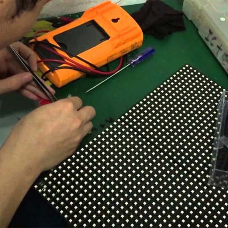 Test The LED Module With A Multimeter
Resistance Detection Method
Issue Identification: Using a multimeter set to resistance mode, test the resistance to ground for each node on the circuit board that fails to light up normally. If the resistance value differs from other nodes, the problem area is determined.
Solution: Check for soldering defects or internal circuit damage at the problematic node. Soldering defects require rework, while internal circuit damage necessitates sending the module back to the manufacturer for repair.
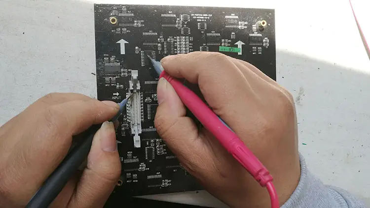
Voltage Detection Method
Issue Identification: Similar to resistance checks, voltage detection involves comparing the voltage to ground for a specific point with that of a normally lit module to identify problematic areas.
Solution: Similar to the resistance detection method.
 Led Module Maintenance
Short Circuit Detection Method
Issue Identification: Set the multimeter to the short-circuit detection mode and check for any short-circuit phenomena. It’s crucial to ensure the circuit board is powered off before short circuit detection to avoid damaging the multimeter.
Solution: Short circuits often result from incorrect circuit layout during LED module production and require replacement by the manufacturer.
Voltage Drop Detection Method
Issue Identification: As ICs comprise numerous miniature components, a current passing through a pin will cause a voltage drop. Abnormal voltage drops can lead to circuit board damage, requiring careful detection.
However, detecting voltage drops has limitations: power must be disconnected during measurement, and high-resistance components cannot be detected.
Solution: Abnormal voltage drops can result from various factors such as overload, internal rusting, or loose contacts, necessitating repairs by the manufacturer.
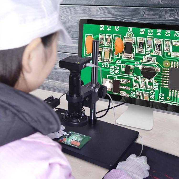 Check Circuit Board
II. LED Module Faults and Solutions
A. Individual LED Module Fails to Light Up:
- Observation of LED power and signal line connections.
- Check if the smart test card can recognize the interface; a blinking red light indicates interface recognition failure. Verify if the LED board shares a common power ground with the test card or if there is a signal-to-ground short causing interface recognition failure.
- Check for soldering defects or shorts on 74HC245 and corresponding enable (EN) signal input/output pins.
- If the entire module displays mixed colors or inconsistent colors (with signal input and correct images), it indicates poor contact in signal transmission lines. Reinsert or replace signal transmission lines for further testing. If replacing good transmission lines does not resolve the issue, check for problems with the pinouts on the transmission line interface.
B. Regularly Alternating Rows are Dark during Scanning:
This issue is usually caused by disconnection, soldering defects, or shorts. Check for the following:
- Check for the above three conditions between the A, B, C, D signal input ports and 245.
- Check for the above three conditions between the A, B, C, D output ports of 245 and 138.
- Check for shorts or ground shorts between the A, B, C, D signals. Note: primarily inspect ABCD row signals.
C. One or Several Rows are Dark when Fully Lit:
Check for circuit discontinuity or soldering, or shorts between 138 and 4953.
D. Only Two or Several Rows (usually multiples of 2, regularly) are Lit during Row Scanning:
- Check for shorts between A, B, C, D signals.
- Check if 4953 outputs are shorted to other outputs.
E. Single or Multiple Points are Dark when Fully Lit (irregularly):
- Replace the faulty LED module and relight to check.
- Measure and observe whether the control pin corresponding to the LED module is shorted to the current row.
F. One or Several Columns are Dark when Fully Lit:
Identify the pins controlling the column on the module and check if the driver IC (74HC595/TB62726, etc.) is connected to the output.
G. Single Point or Column is Bright or Entire Row is Bright and Uncontrolled:
This situation is mainly caused by shorts or IC damage.
- Check if there is a short circuit between the column and the power ground.
- Check if there is a short circuit between the row and the positive power supply.
- Replace the driver IC.
H. Display Confusion, but Signals Output to the Next Panel are Normal:
Check if the STB latch output of 245 is connected to the latch end of the driver IC or if the signal is connected to other lines.
I. Display Confusion, Abnormal Output:
- Check if the clock CLK latch STB signal is shorted.
- Check if there is input and output at 245’s clock CLK.
- Check if the clock signal is shorted to other lines. Note: mainly check the clock and latch signals.
K. Output Issues:
- Observe if the output interface to the signal output IC is properly connected.
- Check if the clock latch signal of the output port is normal.
- Check if the cascaded output data port between the last driver IC is connected to the output interface’s data port or if there is a short circuit.
- Check for signal shorts or shorts to ground.
- Inspect the output cable for integrity.
L. LED Module Displays 8 or 16 points with Rows, Columns, or Single Points not Lighting Up, Remaining Lit, or Dimly Lit:
- Visually inspect corresponding module pins and wires for shorts, soldering defects, or discontinuity.
- Check if shared connection lines between upper and lower modules in each small area (LED modules are divided into upper and lower zones) are intact. If they are, suspect module damage; if not, directly connect using fine wires to eliminate the issue.
- Directly measure individual LED lights on a module using a multimeter. If the LEDs light up normally, suspect an internal short circuit between the circuit board and the module; if not, suspect module damage and replace with the same model LED module.
Method for measuring the brightness of a single lamp with a multimeter:
Set the multimeter to the resistance X1 range. If using an analog multimeter, connect the black probe to the positive terminal of the LED, and the red probe to the negative terminal.
If using a digital multimeter, connect the black probe to the negative terminal and the red probe to the positive terminal. When the LED lights up, it proves that the tested lamp is good. Conversely, if the LED does not light up, then the tested lamp is defective.
M. LED Module Displays Several Rows or the Entire Small Area (LED modules are divided into upper and lower zones) not Lighting Up, Remaining Lit, or Dimly Lit:
- Visually inspect for soldering defects, shorts, or discontinuity in the corresponding row driver, inductor, and integrated circuit. If found, address accordingly.
- Measure the voltage at the output terminals of each row driver with a multimeter (to measure, connect the black probe to GND and the red probe to measure the voltage of each pin); if normal, suspect a discontinuity between the row output terminal and the corresponding module pin; if not, check if the input of the row driver is normal; if so, suspect row driver damage and replace with the same model; if not, check if the output of the corresponding HC138 is normal; if so, suspect a discontinuity between the output of HC138 and the input of the row driver; if not, suspect HC138 damage.
- Replace with a good 16P ribbon cable for testing, measure the voltage at pins 1, 2, 3 of HC138 address input, select terminal 4, 5 (active low), 6 (active high), and integrated circuit power supply. If normal, suspect HC138 damage; if not, continue with step (2).
- Check if the 5V connection line between the two small areas is disconnected; if so, directly connect using the same power supply line (common issue is the entire small area not lighting up or dimly lit).
N. LED Module Displays Small Area (LED modules are divided into upper and lower zones) with No Red or Green:
Visually inspect for soldering defects, shorts, or discontinuity in the corresponding integrated circuit, 26P ribbon cable (1, 2 pins for red signal, 3, 4 pins for green signal), and 5V power supply (replace with a good 26P ribbon cable if necessary).
O. LED Module Displays Small Area (LED modules are divided into upper and lower zones) with the Middle Two Modules Missing Red, Green, or Both Colors are Abnormal from an Abnormal Start to the End:
- Visually inspect the integrated circuit corresponding to the LED module for soldering defects, shorts, or discontinuity, and handle accordingly based on the situation.
- Check if the 5V power supply is normal.
- Measure the voltage at pin 14 of the corresponding HC595 (HC595 measurement should distinguish between red and green integrated circuits, arranged in sequence: red, green (R, G); pin 9 of HC595 is the signal output terminal, pin 14 is the signal input terminal); if normal, suspect HC595 damage (under normal power supply conditions), replace with the same model; if not, check the output terminal voltage of the corresponding HC595, and whether the circuit connection wire is disconnected; if not, suspect HC595 damage, replace with the same model (when replacing the HC595 integrated circuit, pay attention not to disconnect the circuit leads).
P. Continuous Unlit or Abnormal Display:
Check if the signal direction of the first abnormal module’s ribbon cable and power supply line are properly connected. If the LED module’s LEDs are not lit, it indicates improper power line connection or power supply damage; replace the power line or power supply as needed.
If color aberration (mixed colors) occurs, it indicates no signal input to the LED module. Check if the input end of the ribbon cable of the first abnormal LED module is tightly connected. Repeatedly plug and unplug for testing; if the problem persists, replace with a new ribbon cable.
Ⅲ.Troubleshooting Methods
Step 1: Refer to the setting method in the electronic document on the CD to check if the graphics card settings are configured correctly.
Step 2: Check if various interfaces are connected, such as DVI ports, Ethernet ports, serial ports, and the connection between the main control card and the computer’s PCI slot. Since interface cables are specific, there is no possibility of plugging them in incorrectly.
Step 3: The number of LED power supplies needs to match the LED cabinet. Insufficient power supply for the LED display screen can cause flickering when displaying white screens.
Step 4: Check if the green light of the sending card flashes regularly: If it flashes, proceed to Step 6; if not, restart. Before entering the Windows system, check if the green light flashes regularly. If it does, proceed to Step 2. If the problem persists, one of the sending card, graphics card, or DVI cable may be faulty. Replace them respectively and repeat Step 3.
Step 5: Follow the software instructions for settings or reinstall and then set up again until the green light of the sending card flashes. Otherwise, repeat Step 3.
Step 6: Check if the green light (data light) of the receiving card synchronously flashes with the green light of the sending card. If it flashes, proceed to Step 8. Check if the red light (power light) is on. If it is, proceed to Step 7. If not, check if the yellow light (power protection) is on. If it’s not on, check if the power supply is reversed or if there’s no output. If it’s on, check if the power supply voltage is 5V. If so, turn off the power, remove the adapter card and ribbon cable, and try again. If the problem persists, it’s a receiving card failure. Replace the receiving card and repeat Step 6.
Step 7: Check if the network cable is properly connected or too long (must use standard CAT5 cable, with a maximum length shorter than 100 meters without repeaters). Check if the network cable is made according to standards (please refer to the installation and setup manual). If the problem persists, it’s a receiving card failure. Replace the receiving card and repeat Step 6.
Step 8: Check if the power indicator light of the LED screen is on. If it’s not on, proceed to Step 7, and check if the pin definition of the adapter card interface matches the LED module.
Note: After most screens are connected, some screens may not display or show abnormal images. This is generally due to loose RJ45 connectors or the receiving card power not being connected, resulting in no signal transmission. Reconnecting the network cable (or replacing it) or connecting the receiving card power (paying attention to the direction) can usually solve the problem.
Ⅳ.Other Maintenance Methods
Maintenance of LED Dead Pixels (Out-of-Control Points):
After confirming through single-lamp detection that an LED is damaged, select one of the following maintenance methods according to actual needs.
Front Maintenance: Use a corresponding screwdriver to remove the fixed mask screws from the front, gently remove the mask, and replace the LED (please follow the LED replacement method below). After replacing the LED and sealing the colloid, restore the original mask, tighten the screws (be careful not to press the LED), and carefully remove any remaining colloid from the LED surface.
Back Maintenance: Use a corresponding screwdriver to remove the screws from the back and place them aside. Unplug the signal cable, but for safety, do not unplug the power connection to prevent accidents. Carefully remove the module from the sheet metal hole, move it to the back of the cabinet, and then follow the front maintenance method to maintain and replace the LED for each individual module.
LED Replacement Method:
Use a sharp tool (such as tweezers) to remove the colloid around the damaged LED, exposing the LED pins. Hold the LED with tweezers in your right hand, control the temperature of the soldering iron at around 40 degrees Celsius with your left hand (excessive temperature will damage the LED), make contact with the solder, and melt it slightly.
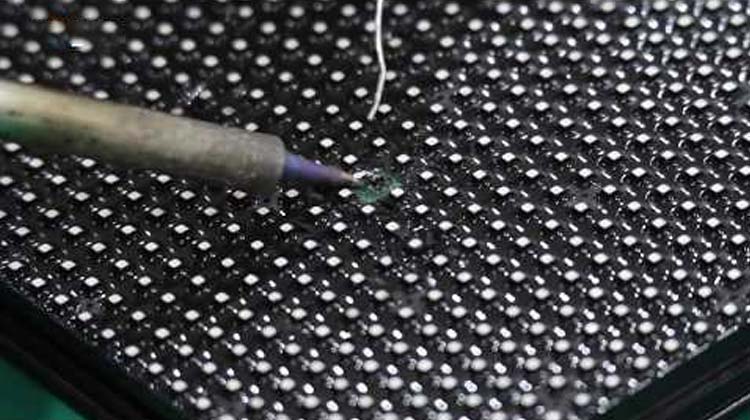 Repair LED Lamp Beads
The dwell time should not exceed 3 seconds. If it exceeds 3 seconds but does not meet the disassembly requirements, it needs to be cooled down and tried again.
Then use tweezers to remove the LED, and then correctly insert the LED into the holes on the PCB circuit board (the long leg of the LED is the positive pole, the short leg is the negative pole, and the “square hole” on the PCB is the positive pin hole of the LED, and the “round hole” is the negative pin hole of the LED), melt a little solder wire, adhere it to the soldering iron tip, adjust the LED direction with tweezers to make it smooth, and solder the LED to the PCB. Seal the LED with the same type of colloid (pH = 7).
This guide provides comprehensive troubleshooting and solutions for various LED display screen issues. It’s intended to assist both engineers and customers in effectively addressing problems and minimizing downtime.

