

What is SMD (surface mount device)?
SMD (surface mount device) is an electronic device that places components directly on the surface of a PCB. It was originally developed by IBM in the United States. After 20 years of development, it has gradually become popular in the market and has gradually replaced DIP (through-hole dual in-line package) has become the mainstream packaging method for LED modules.
What is SMT (Surface Mount Technology)?
In addition to SMD, there is another word that is similar to it and is easily confused by us – SMT (Surface Mount Technology).
SMT refers to products that use SMD packaging technology. This is significantly different from the DIPT (through-hole dual in-line package technology) we mentioned earlier.
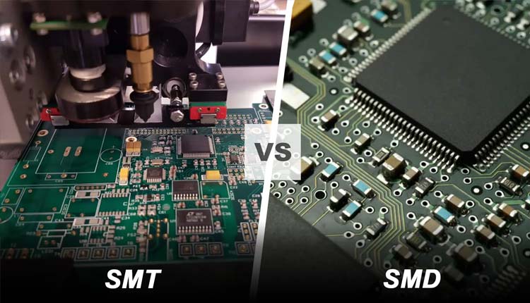 SMT And SMD
SMT is suitable for use on more precise objects, while DIPT is suitable for use on larger objects, such as large transformers, high pixel pitch LED modules (that is, LED modules with a pixel pitch greater than 10mm), and heat dissipation power of semiconductors.
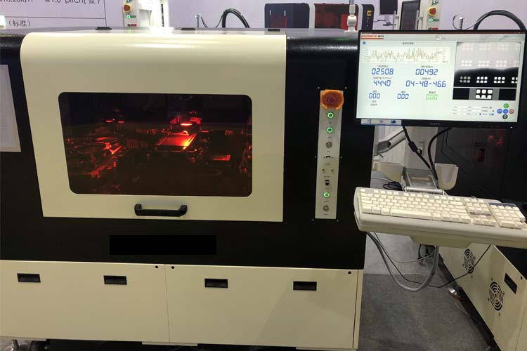
 SMT Production Line
SMT components are typically much smaller than through-hole components and come in a variety of different types depending on the type of application, such as short pins, leads, flat contacts, solder ball (BGA) matrices, or component body terminals.
Through-hole components, on the other hand, usually have longer leads and are therefore very easy to distinguish visually.
SMT production process
First, we need to align the PCB template with the surface of the circuit board, and then use a squeegee to evenly apply the solder paste to ensure that the pads are evenly distributed and have a controlled amount of suitable solder paste.
Secondly, the components are accurately installed into their respective locations on the board using a pick-and-place machine or manual placement. Note that when operating manually, be sure to grasp the precise control position. If you find that it is not completely aligned, you can gently move the circuit board to avoid misalignment. Because a misaligned circuit board will eventually cause damage to the circuit board.
Third, the circuit board passes through a reflow oven, which exposes the circuit board to infrared radiation, thereby increasing the temperature of the solder paste. When the solder paste reaches the melting point, solder joints will form and stick firmly to the circuit board.
Next, an AOI machine or automatic optical inspection machine is used to conduct multiple quality checks on the circuit board. The current inspection is completed by visually inspecting the board, such as component alignment and checking for solder bridges.
Fourth, use low-voltage voltage to conduct a power-on test on the circuit board to check whether the lines and solder joints inside the circuit board can pass current to ensure that the circuit board can be used normally.
Introduction to the advantages of SMT
Manufacturing more precise PCB boards
Since SMD components have shorter or even no pins, more precise PCB boards can be manufactured using SMT. Taking LED modules as an example, it is very difficult to use through-hole insertion technology to produce LED modules with a pixel pitch of less than 10mm, let alone LED modules with smaller pixel pitches such as P2 and P1.
Efficient assembly
The SMT assembly process is purely automated, and the error rate is less than one in 100,000. During the automatic PCB assembly process, it is safe and fast, maximizing the assembly efficiency.
Use stable solder connections
SMD components ensure a secure hold on the circuit board. This is because each pole has two pads used by the manufacturer. Even smaller electronic PCB components can be placed. Moreover, when the machine operates the PCB, it is more stable and can better protect the PCB from being interfered by external factors.
Reliable processing
To make surface mount devices, some manufacturers use LCP, a high-performance plastic. It ensures optimal dimensional stability and precise grid alignment. The substance is highly heat-resistant to solder, ensuring a smooth, consistent and reliable SMD connection method.
In addition, in order to ensure the smooth progress of PCB services and reduce rework costs, AOI inspection will be performed after the surface mount installation is completed. This inspection equipment is placed at the exit of the reflow soldering.
Long term tolerance
The machine undergoes rigorous endurance testing before leaving the factory, so it can run at high frequency for a long time.
 Backlight Crystallizer
Components needed when packaging SMD
Discrete SMD resistors
There are two basic variations of surface mount resistors:
Thick Film:
Unlike axial resistors where a resistive film is deposited on a circular core, thick film surface mount resistors are made by masking the resistive film on the surface of a flat, high-purity aluminum oxide substrate. The resistance value was calculated by changing the resistive slurry composition before screening and laser trimming the film after screening.
Thin Film:
Tin film resistors have solderable terminals on the sides and a protective layer on top. They have a resistive element on a ceramic substrate. On ceramic substrates, the block has an adhesive layer, a nickel barrier underplating, and an impregnated or electroplated solder overlay. The nickel barrier is critical to maintaining the solderability of the terminals.
Network resistance (RA/RN)
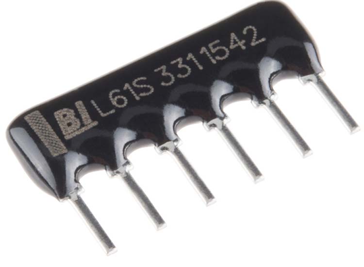 Network Resistance
A network resistor is composed of multiple resistors integrated together, so it is also called a resistor. When packaged into an integrated circuit, it can also be called an integrated resistor.
In the network resistor’s advanced ceramic chip, there are metal electrodes at each end to connect the thick film resistive elements. Typically the chip will contain multiple resistors of similar size at the same time, making it ideal for digital memory circuits.
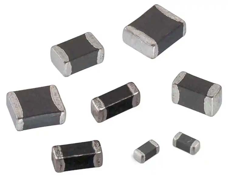
Chip capacitor
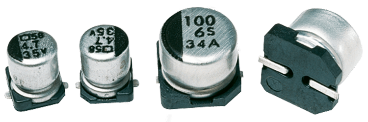 Chip Capacitor
Chip capacitors are also called multilayer chip ceramic capacitors (MLCC) or monolithic capacitors, which are in the shape of rectangular blocks. It is a ceramic chip formed by stacking ceramic dielectric diaphragms with printed electrodes (internal electrodes) in a staggered manner, and then sintering them at a high temperature in one go.
Then a metal layer (external electrode) is sealed on both ends of the chip to form a monolithic-like structure, hence the name monolithic capacitor. It is an energy storage device, and the capacitance unit is Farad (F).
Chip inductor
 Chip Inductor
Chip inductors, like chip capacitors, have many names, such as power inductors, high current inductors, surface mount high power inductors, etc.
Its main function is to convert electrical energy into magnetic energy and store it as a basic surface mount component. The inductance unit is H. There are two types of chip inductors: with magnetic cover and without magnetic cover. They are mainly composed of insulator and enameled wire.
SMD transformer
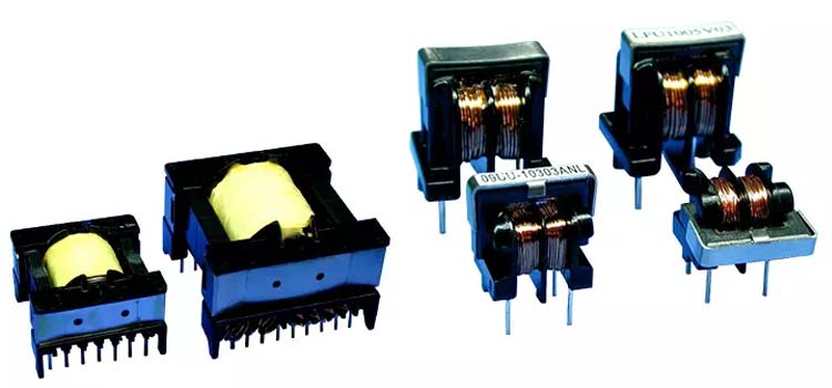 Transformers
A transformer is a type of AC voltage that is manufactured based on Faraday’s law of electromagnetic induction.
Although SMD transformers are different from conventional transformers in terms of voltage, current, winding capacitance, etc., since the overall structure and principle are the same, we will not make more detailed distinctions.
Diodes and transistors
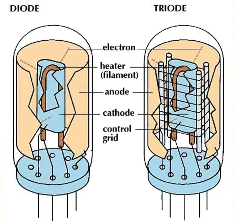 Diode And Triode
Diodes are composed of two semiconductor materials, have unidirectional conductivity, and are polar components. Therefore, the current entering from the positive electrode encounters negligible resistance. But if it’s the other way around, and current enters through the negative pole, the resistance is high.
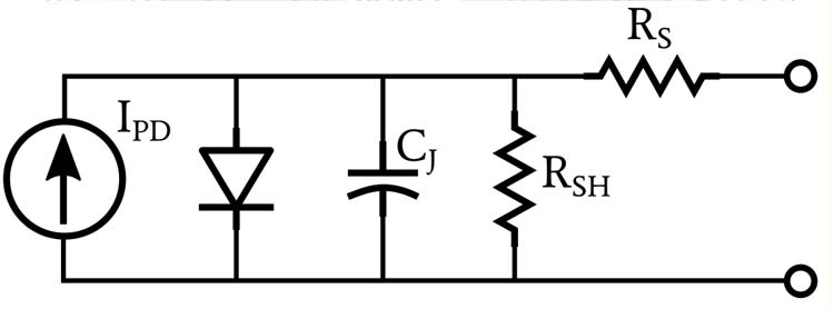 Photodiode Equivalent Circuit
The triode is a more complex component with three electrodes: emitter, base and collector. Its main function is to amplify weak electrical signals and at the same time keep the output voltage of the circuit stable in SMD.
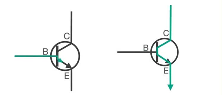 Circuit Control Diagram Of Triode
Chip integrated circuit
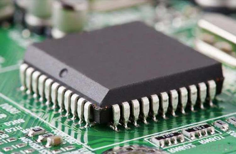 Integrated Circuit
SMD integrated circuits combine components such as diodes, capacitors, inductors, and resistors on small semiconductors called integrated circuits (ICs).
Crystal oscillator
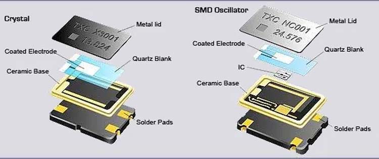 Crystal Oscillators
A crystal oscillator is a two-terminal quartz device with a silver coating on it. Their function generates the oscillation frequency and thus the device’s clock signal.